Experiments
About
Reources
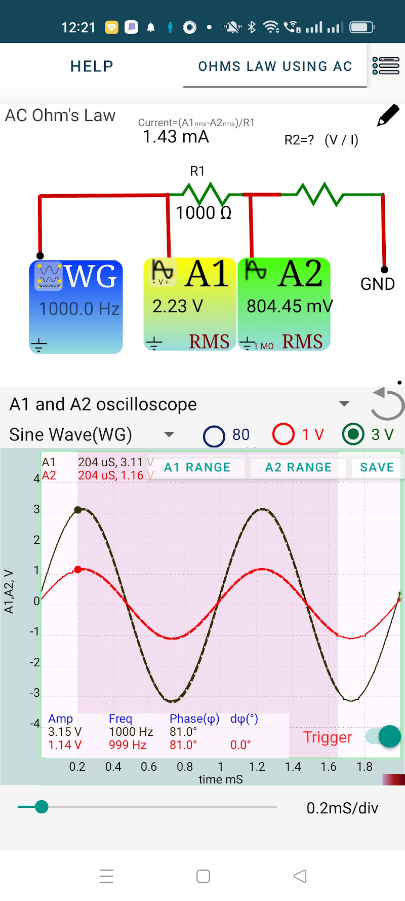
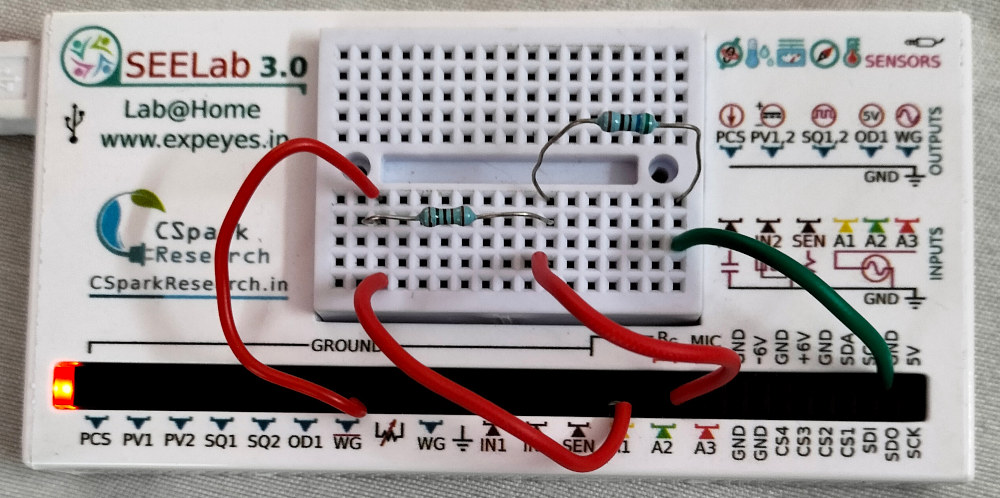
The objective of this activity is to explore the behavior of resistors under an applied AC voltage. Two resistors are connected in series from the AC voltage sorce WG to ground. The applied voltage is monitored by A1 and the voltage across R2 is monitored by A2. The voltage across both R1 and R2 are plotted as a function of time. R1 is 1000 ohms and we have used a 560 Ohm resistor as R2.
By selecting a region of the graph, the graph is mathematically analyzed to obtain the Peak voltage, frequency and the phase difference between the traces. We assume that the same amount of current flows through both R1 and R2 (neglecting the 1M input impedance of A2).
from the results
The same amount of current flows through R2. According to Ohm’s law R2 = 1.13 / 2.01mA = 562 Ohms, agreeing within the experimental error.
From the graph, it can be seen that the voltages across both the resistors are in phase. For a resistor the voltage and current are in phase. So we can consider the phase of the voltage across the resistor are the phase of current.
The RMS values of the voltages measured by A1 and A2 are displayed on the icons. In the case of a sine wave, the RMS value is obtained by dividing the peak value by $ \sqrt{2} $. The displayed RMS value is calculated from the instantaneous values for a full cycle, by summing the squares of them and then taking the square root.