Experiments
About
Reources
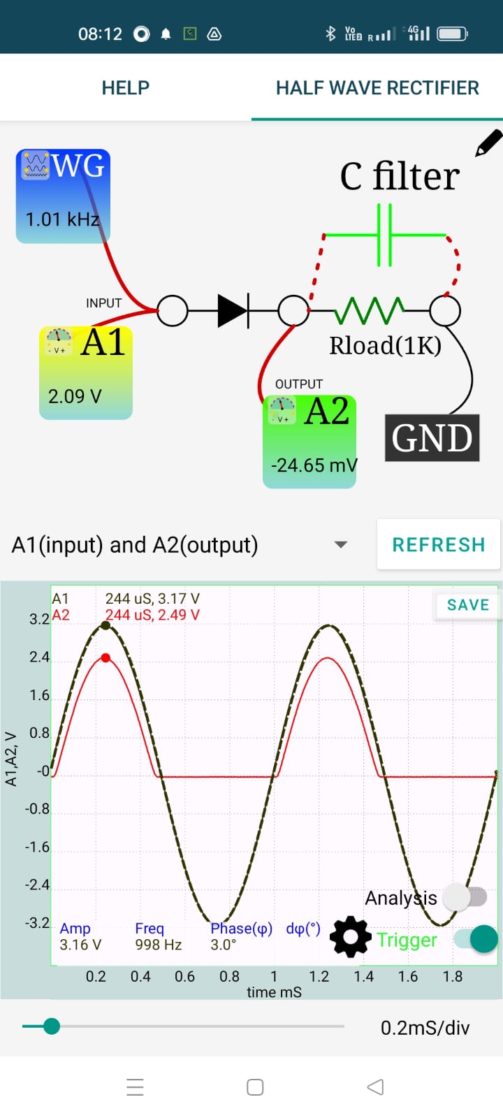
The terminal WG provides the AC signal and the oscilloscope channels A1 and A2 measures the applied voltage and the voltage after the diode.
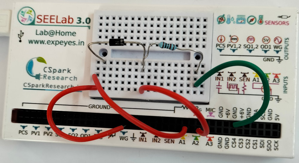
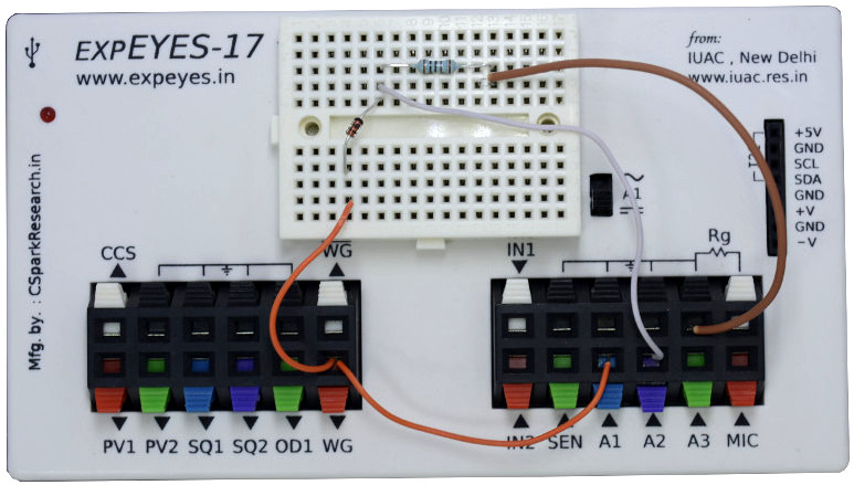
Results and the experiment setup are shown below.
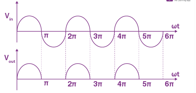
Carefully examine the input and output waveforms shown above. Most of the textbooks show a picture like the one shown below (This picture is taken from the website of a multi-billion dollar education firm in India). The actual result differes from what is shown in the textbooks.
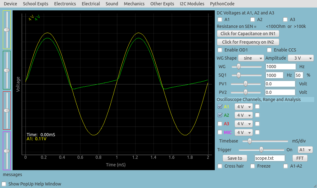
Every diode has a junction capacitance that acts like a capacitance connected in parallel to the ideal PN junction. Junction capacitance of 1N4148 is only 4pF but 1N4007 has a junction capacitance of 20pF. The rectified output, without external load resistor, for 1N4007 is shown below. The 1MOhm input impedance of channel A2 will be always present. The voltage appearing on the negative half is due to capcitive coupling. This will not be observed at low frequencies, like 50hz. When the 1 kOhm load resistor is connected, the charge induced through the capacitor will not be sufficient to generate a measuable voltage.
The output after adding a 1uF capacitor for filtering is shown below.
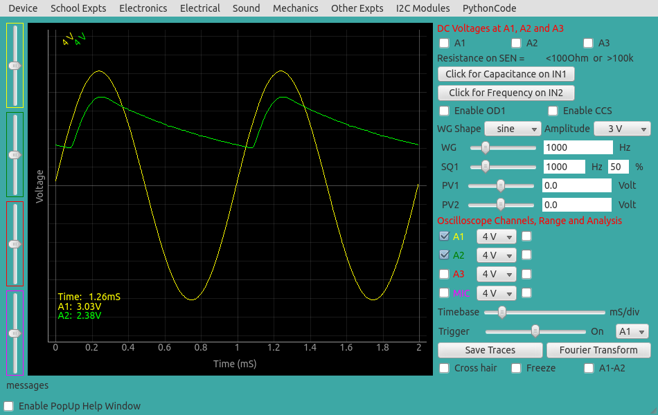
With increasing RC value, the ripple reduces.