Experiments
About
Reources
The schematic is wired as shown in the diagram below. The output of 555 is monitored on channel A1, and also connected to IN2 for frequency and duty cycle measurement. The charging waveform may be monitored on A2. The capacitor from pin5 to ground is for noise reduction.

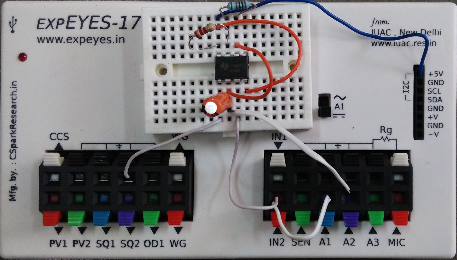
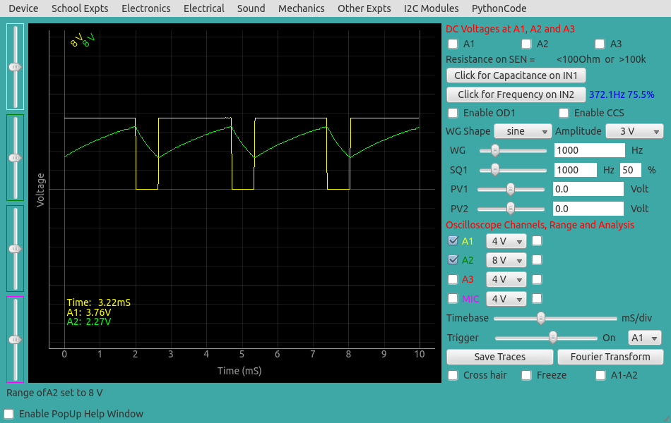
We have used R1 = 2.2K, R2 = 1K, C = 1uF . The calculated frequency and duty cycle are 343.6 Hz and 76.2%.
The measured values are shown in the figure below.
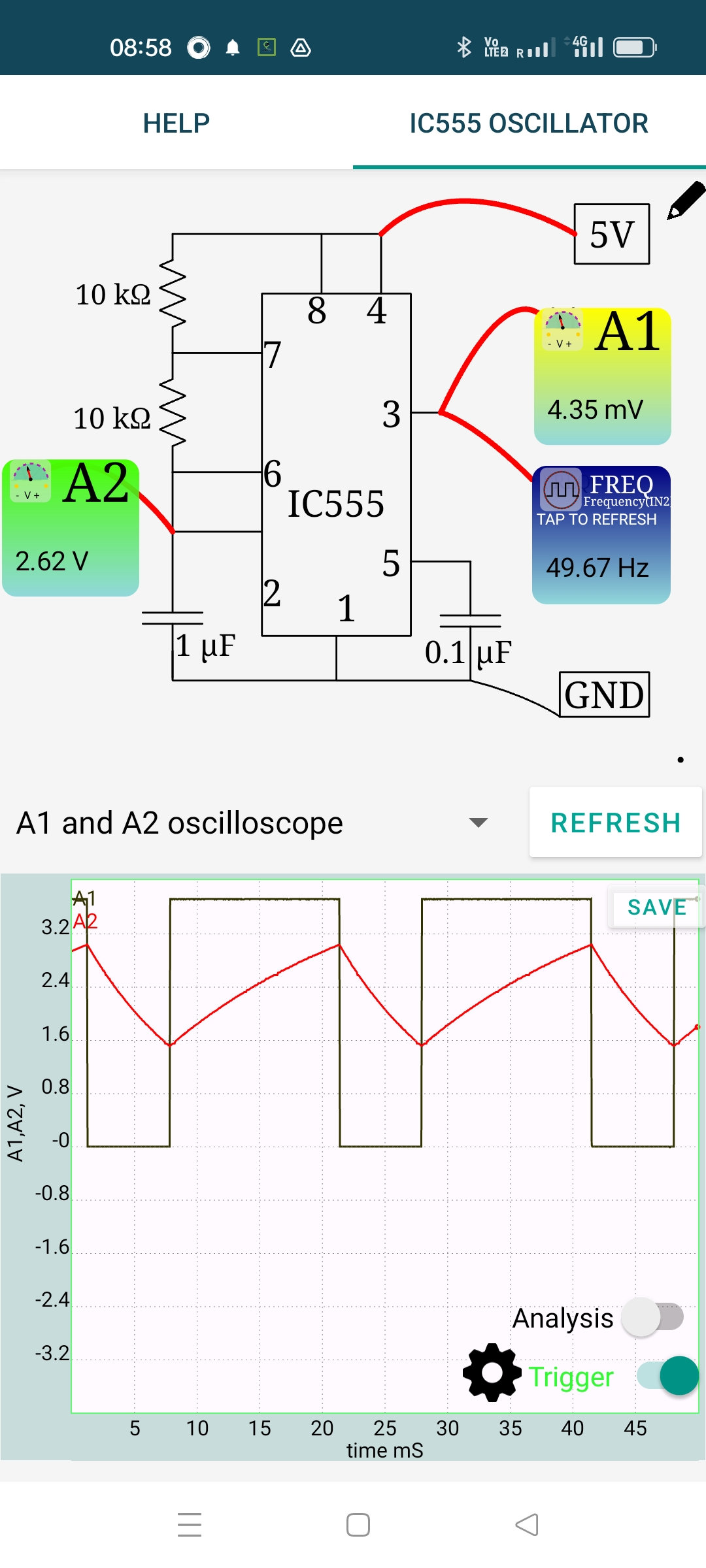
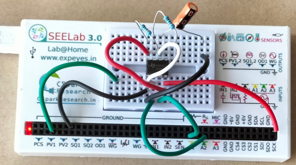
The same experiment repeated using SEELab3 on Android. The component values are different. The experimental setup and the screenshot of the result are shown below. Frequency and duty cycle for various resistor and capacitor values may be calculated from this External Link. For the RC values used, the calculated frequency is 48 Hz, and the measured value is 49.67 Hz, expected considering thee tolerance values of the components used.