Experiments
About
Reources
Applying Kirchhoff’s law to a series LCR circuit gives
$ L\frac{di}{dt}+iR+\frac{q}{C}=v_m\sin\omega t $
Solving this equation will gives
$ i_m = \frac{v_m}{\sqrt{R^2+(X_C-X_L)^2}} $
$ Z=\sqrt{R^2+(X_C-X_L)^2} $ is the total impedance of the circuit. Both $ X_L=2\pi f L $ and $ X_C=\frac{1}{2\pi f C} $ depends on frequency. $ X_C $ decreases with frequency and $ X_L $ increases.
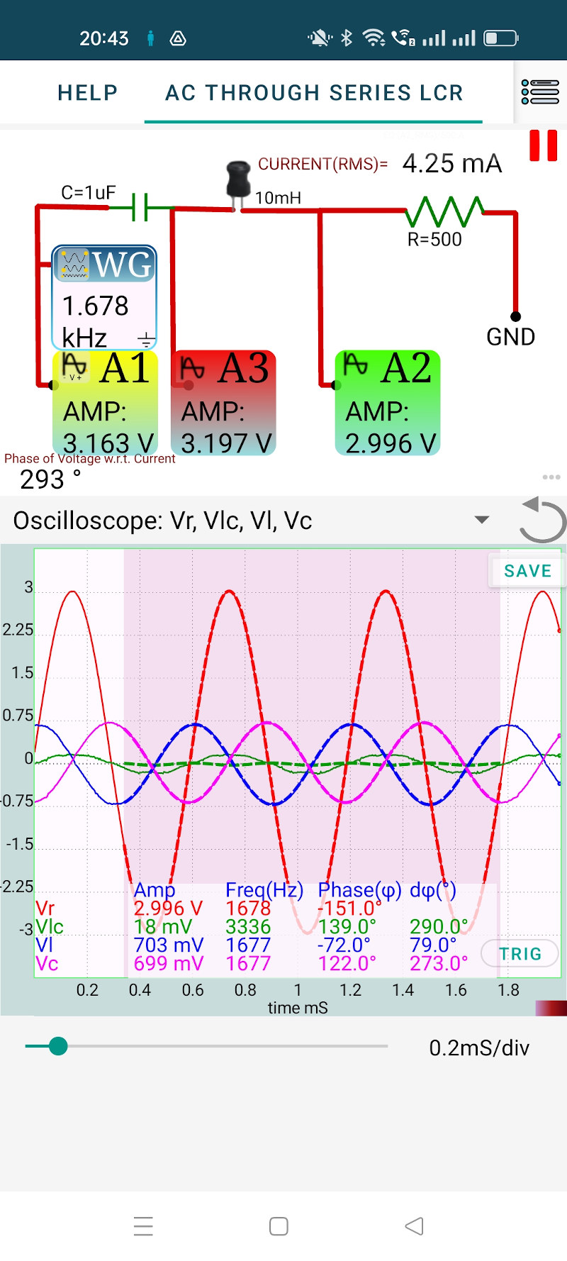
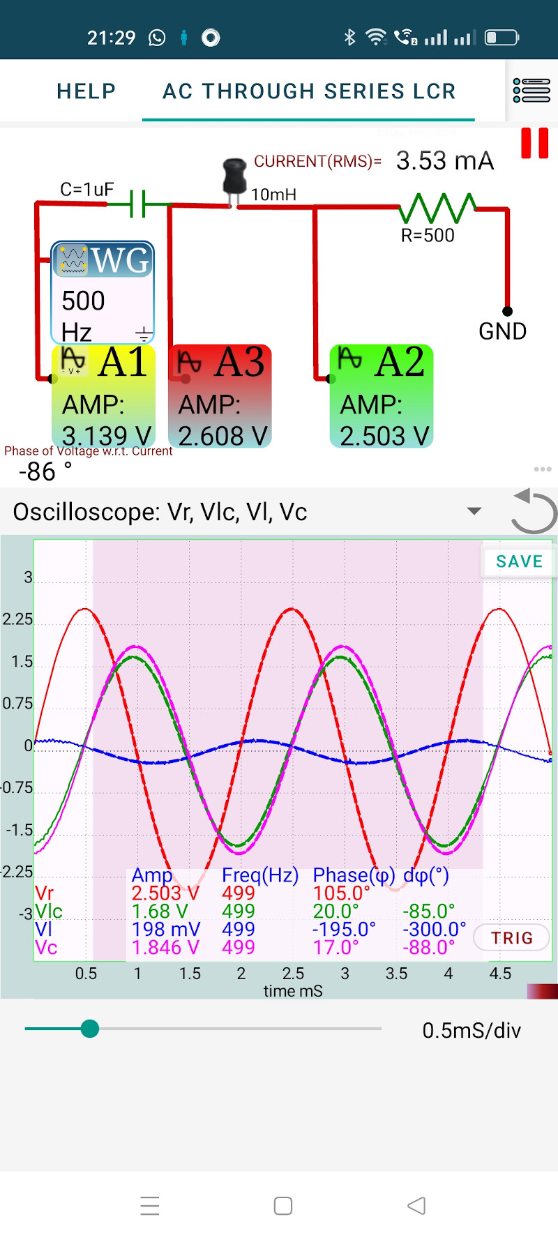
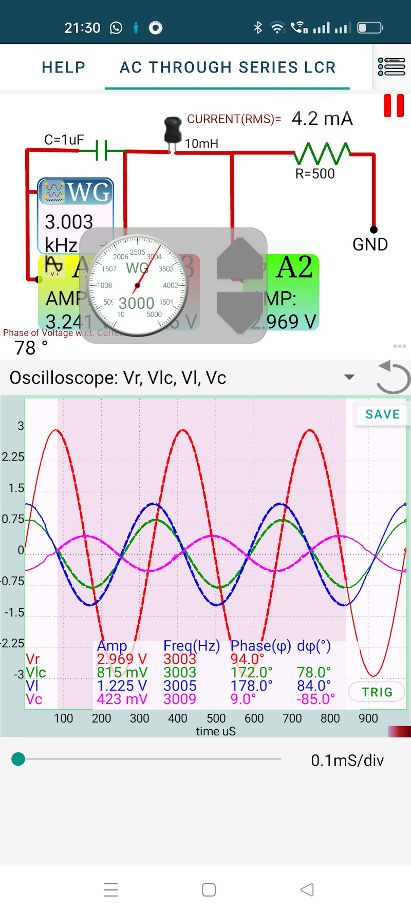
The screenshots below shows the results, for 500 Hz and 3000 Hz. At lower frequencies the capacitor offers higher resistance to the current flow and the voltage across it is higher. At higher frequencies the voltage drop is more across the inductor.
At some frequency $ (X_C-X_L) $ becomes zero and the impedance Z will become equal to R. This frequency is called the resonant frequency. At resonant frequency the total reactance offered by the capacitance and the inductor become zero.
For the selected LCR values the resonant frequency = $ \frac{1}{2\pi\sqrt{LC}} = 1591 $Hz. Actual resonant frequency may be slightly different because of the tolerance if the component values.
At resonance the total volatge across LC goes to zero (It does not happen here because of the 20 Ohms resistance of the inductor winding). The individual voltages across L and C becomes equal inamplitude and opposite in phase.