Experiments
About
Reources
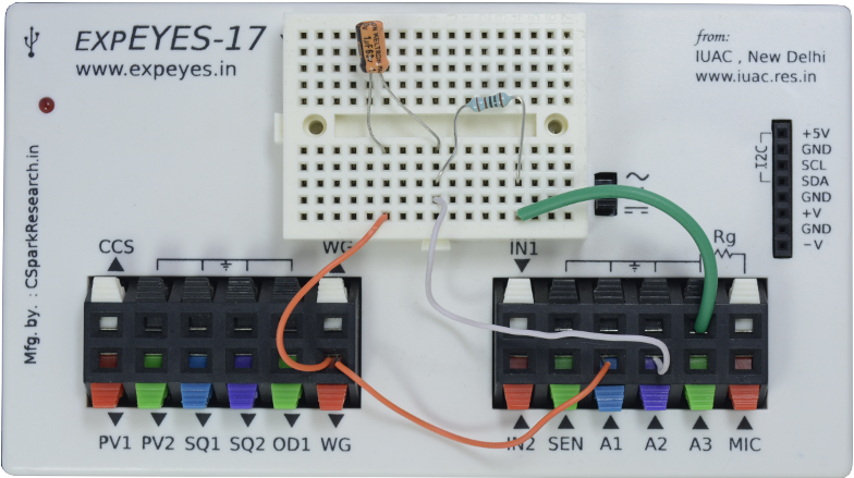
The objective is to study the behavior of a RC series circuit under an applied sinusoidal voltage. The resulting voltage amplitudes across the elements and their phase relationships are measured. The connections are shown in the screenshot below.
We have chosen a 1uF capacitor and 1000 Ohm resistor. The applied frequency is chosen as 150 Hz, because for the chosen RC values the voltages are almost equally divided and easy to visualize from the graph.
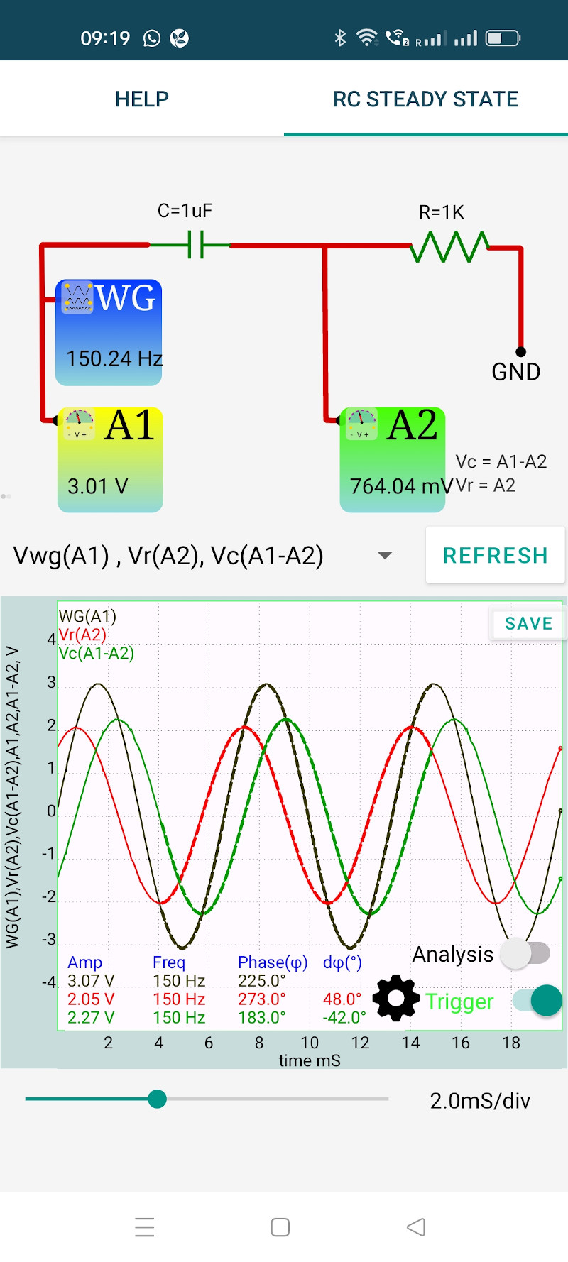
An AC voltage is applied to the RC circuit. The phase of current is same as the voltage across the resistor. The output shows three traces:
It can be seen that the voltage across the capacitor lags behind the current by $ \frac{\pi}{2} $. The phase difference between the applied voltage and current is given by $ \phi=tan{^1}(\frac{Z_C}{R}) $, where $ {Z_C} $ is $ \frac{1}{2\pi fC} $. This phase difference between the traces also is displayed. For R=1k, C=1uF and f=150 Hz the calculated value is $ 46.79^o $ and the measured value is $ 48^o $. The difference is due to the tolerance values of the components.
The measured values of the applied voltage, voltage across the capacitor and the voltage across the resistor are also shown. Vector addition should be used to get the total voltage from the voltages across R and C.
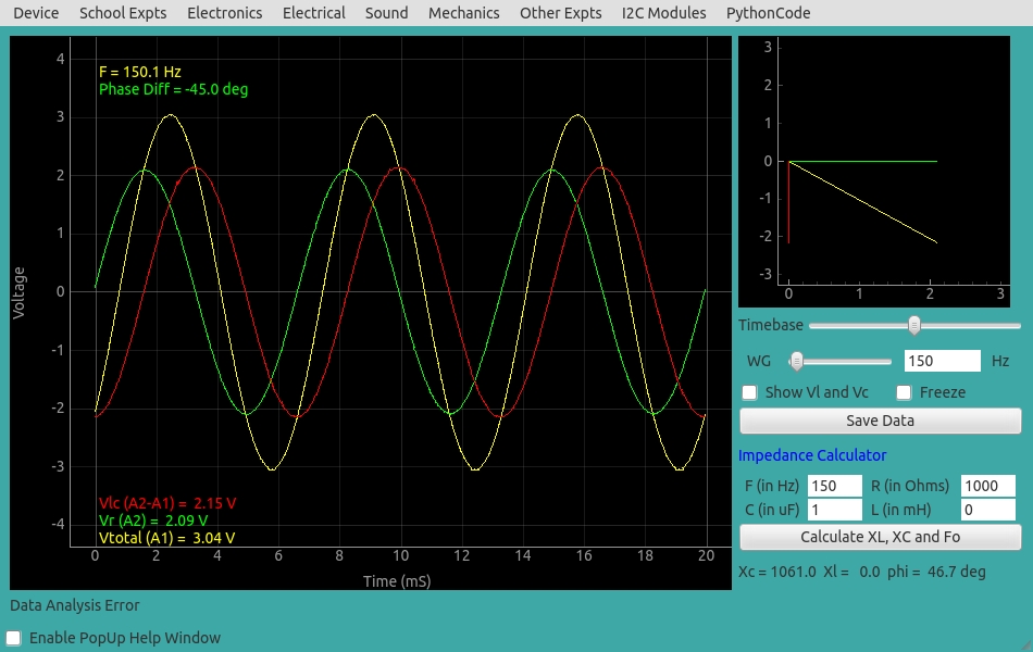
Result of the same experiment done on the PC is shown below.