Experiments
About
Reources
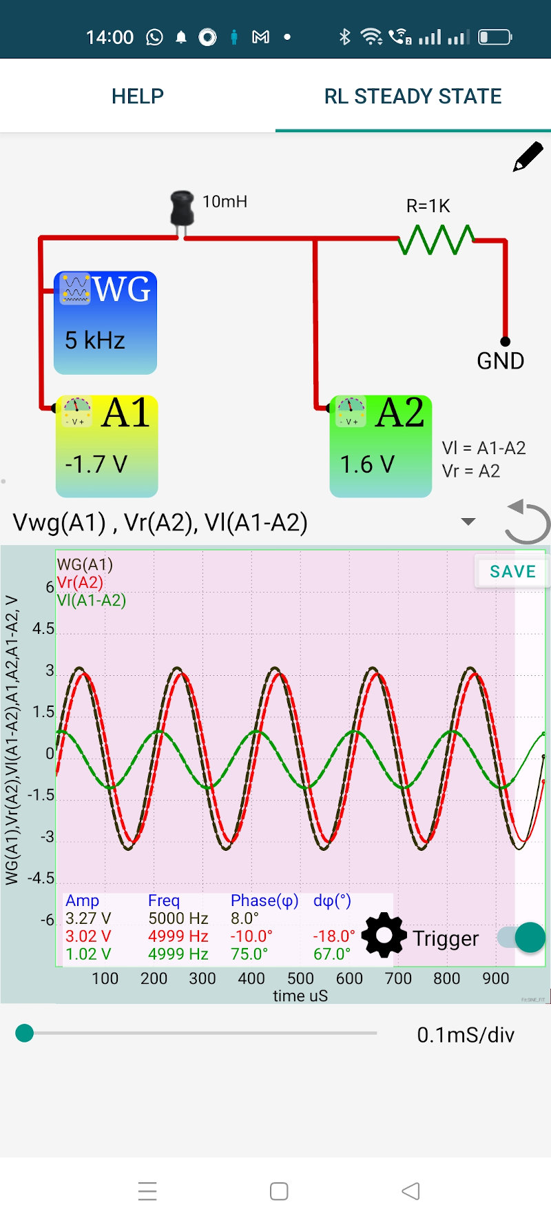
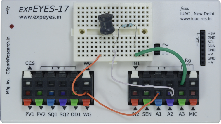
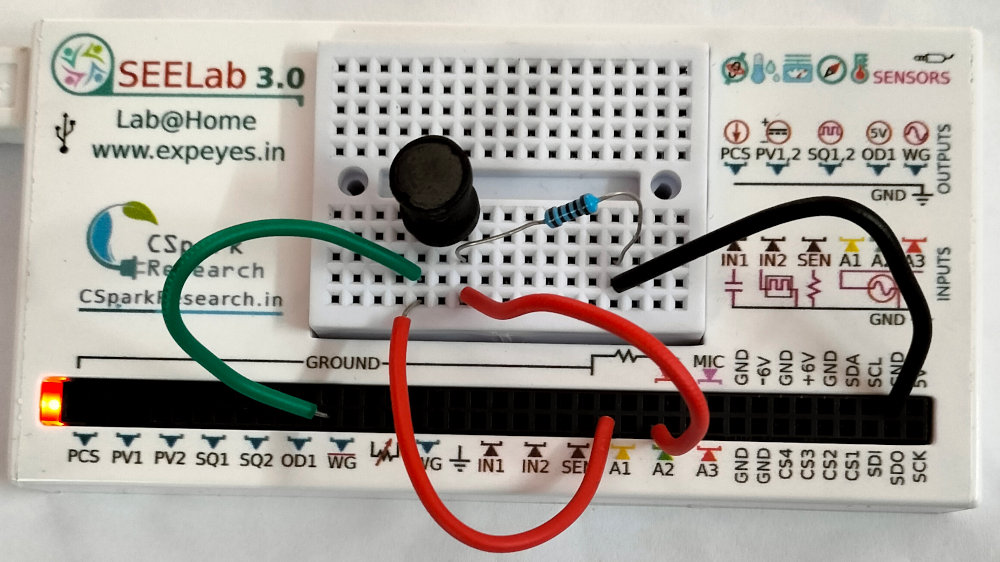
The objective is to study the behavior of a RL series circuit under an applied sinusoidal voltage. The resulting voltage amplitudes across the elements and their phase relationships are measured. The connections are shown in the screenshot below.
We have chosen a 10mH inductor and 1000 Ohm resistor. The applied frequency is chosen as 5000 Hz.
An AC voltage is applied to the RL circuit. The phase of current is same as the voltage across the resistor. The output shows three traces:
It can be seen that the voltage across the inductor is ahead of the current by $ \frac{\pi}{2} $. The phase difference between the applied voltage and current is given by $ \phi=tan{^1}(\frac{Z_L}{R}) $, where $ {Z_L} = {2\pi fL} $. This phase difference between the traces also is displayed. For R=1k (plus 20 Ohms), L=10mH and f=5000 Hz the calculated value is $ 17.12^o $ and the measured value is $ 18^o $. The Ohmic resistance of the inductor should be included in the calclations.