Experiments
About
Reources
The objective of this experiment is to explore the phase relatioships of voltage and current across a capacitor in an AC circuit. We also calculate the capacitive reactance from the current and voltage, using Ohm’s law. The 1K resistor and A2 constitutes our ammeter.
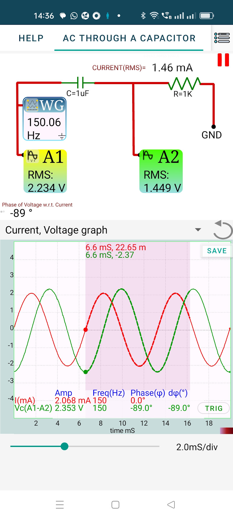
The amplitude, frequency and phase are displayed when a region is selected. It can be seen that the current is at the peak when the voltage across the capacitor is at zero, means the voltage is lagging by 90 degrees.
Capacitive reactance, $ X_C=\frac{V_C}{I_C}=\frac{1}{2\pi fC} $, implies $ C=\frac{I_C}{V_C 2\pi f }$ = 932.5 uF
Measurement of the capacitor by using IN1 gives 937 uF. This confirms that the results agree with the theory within the experimental error.
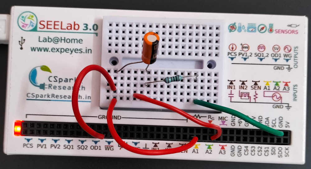
This experiment is performed by capturing the applied voltage and the voltage across the resistor. Voltage across the capacitor is obtained by subtraction.
The function capture2(number_of_samples, time_gap) returns two sets of (time, voltage) vectors. They are mathematically fitted with the equation $ V=V_0 \sin(\omega t + \theta) + C $, to extract the Amplitudes and Phases.
$ ({\theta}_1 - {\theta_2}) $ gives the phase difference between the voltage and current waveforms.
The ratio of Amplitudes gives the Capacitive reactance