Experiments
About
Reources
The objective is to explore the phase and amplitude relationships between the current and the voltage of an AC signal applied to a resistor. The method of current measurement is explained in the section on Ohm’s Law. In this experiment, the 1000 Ohm resistor and A2 forms the ammeter. Voltage across R1 is taken as the current waveform. This is plotted along with the voltage across R2.
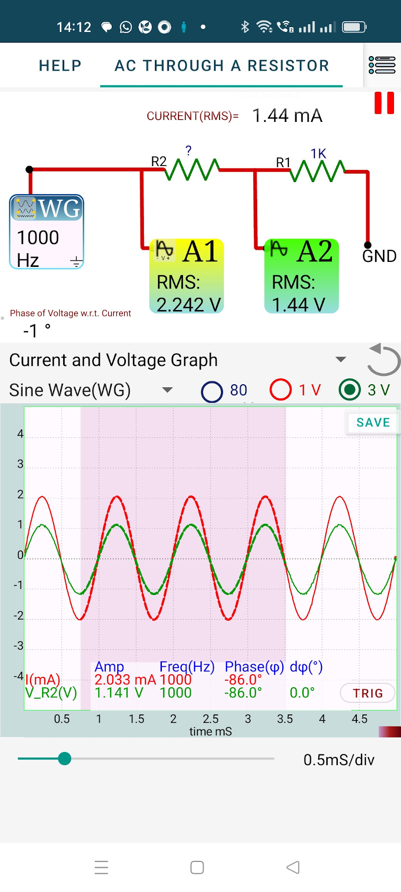
By selecting a region of the graph, the graph is mathematically analyzed to obtain the Peak voltage, frequency and the phase difference between the traces. We assume that the same amount of current flows through both R1 and R2 (neglecting the 1M input impedance of A2).
from the results
The RMS values of the voltages measured by A1 and A2 are displayed on the icons. In the case of a sine wave, the RMS value is obtained by dividing the peak value by $ \sqrt{2} $. The displayed RMS value is calculated from the instantaneous values for a full cycle, by summing the squares of them and then taking the square root.