Experiments
About
Reources
The magnitude and direction of current from a drycell is constant in time. Such currents are called Direct Current (DC). In the previous section we have seen the voltage induced on a coil by a rotating magnetic field, that changes direction and magnitude periodically.
To understand the behavior of AC, we need to plot the voltage as a function of time, that requires an oscilloscope. The input terminals A1, A2 and A3 are oscilloscope inputs. It is safer to study AC using lower voltages. The terminal WG generates a sinusoidal AC signal having a peak value of 3 volts. It’s frequency can be varied from 5Hz to 5000 Hz. The terminal PV2 can be used as a DC source. The voltage output can be set anywhere between -3.3 volts and +3.3 volts.
In addition to these two signals we also plot a square wave that swings between 0 and 5 volts (or the supply voltage provided by the USB port, could be slightly smaller for phones).
Procedure:
Trace of A3 is a horizontal line, no change in voltage with time. That means it is pure DC. Trace on A1 changes between -3 volts and +3 volts. The variation is sinusoidal. The two graphs gives some idea about AC and DC voltages.
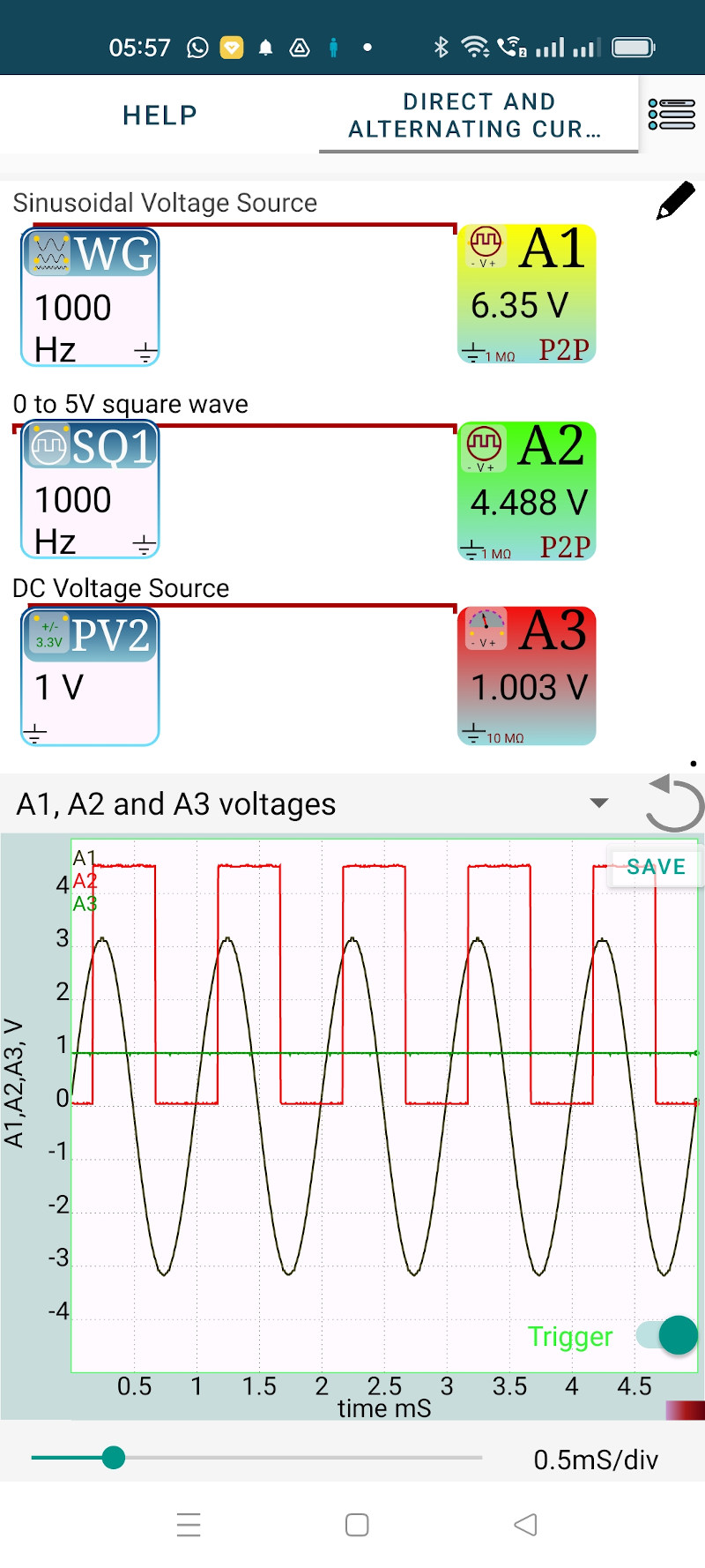
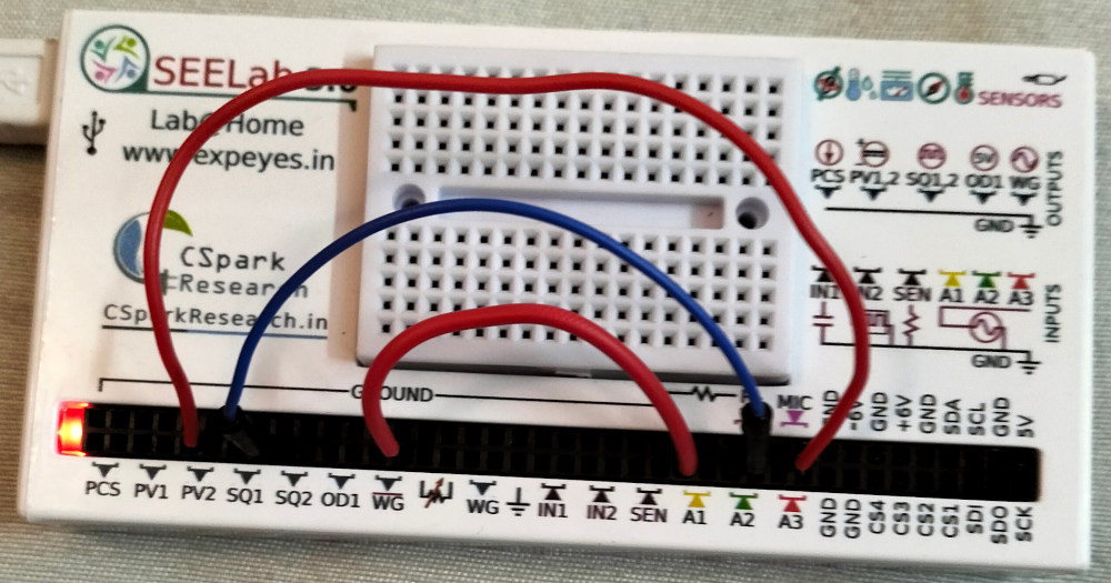
What about SQ1 displayed on A2. The voltage swings between 0 and 5 volts. Do you call it AC or DC ?
You cannot classify a voltage as AC or DC because it could be a combination of both, like ripple of a DC power supply. The 0 to 5V swing can be considered as a 2.5 volts AC superimposed on a 2.5 volts DC.
Exercise: Insert a 0.1 uF capacitor o the path of SQ1 and observe the change in the display.
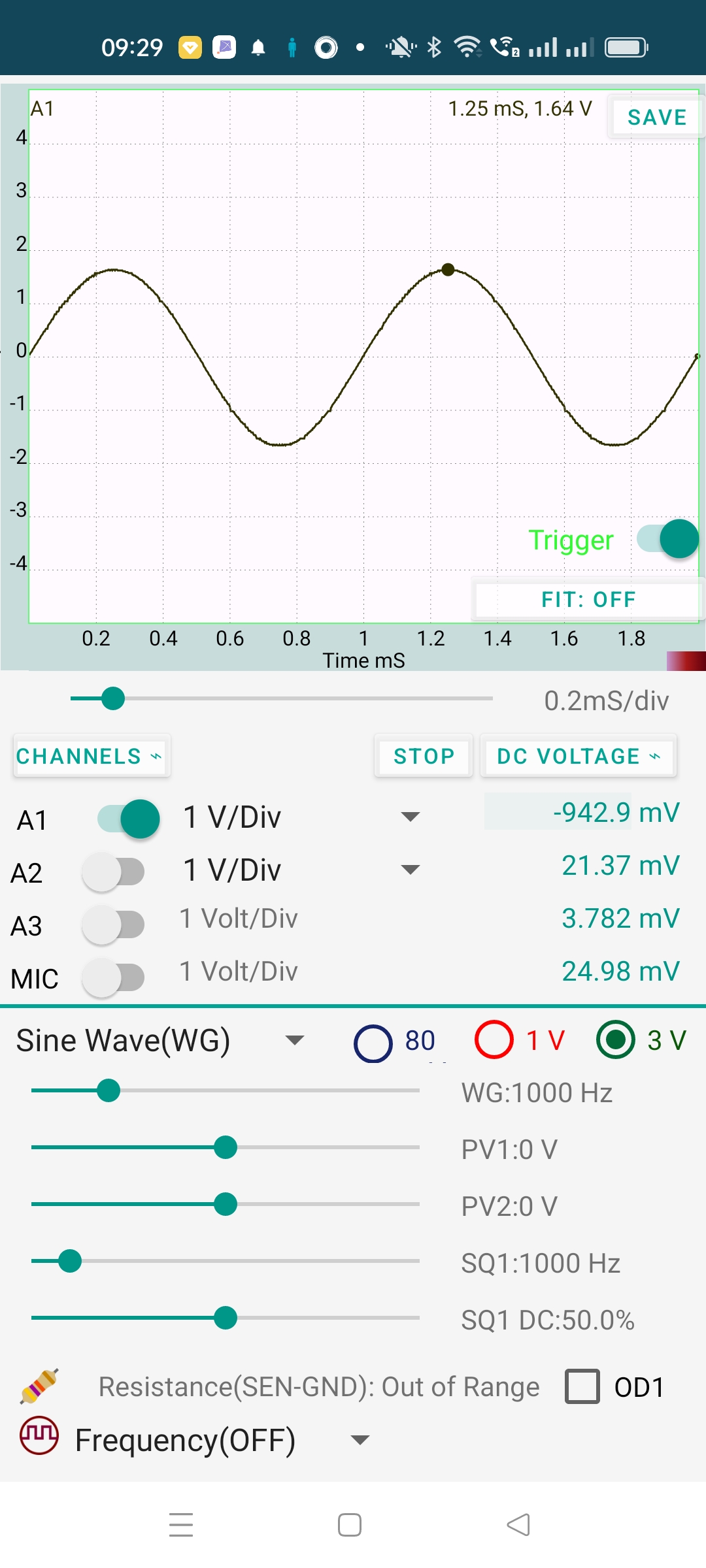
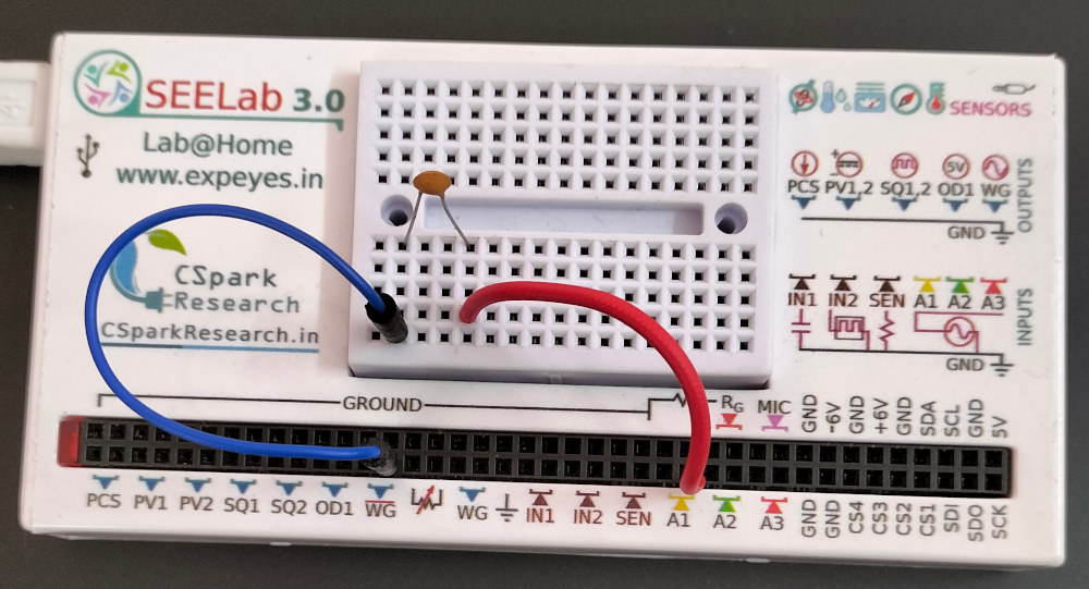
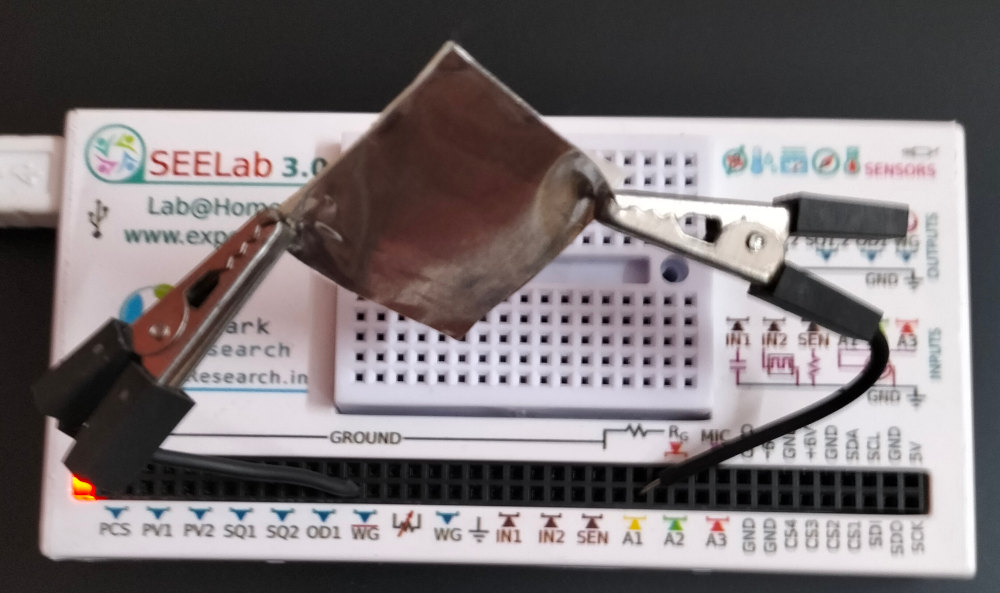
A DC cannot pass through a capacitor because the plates are separated by an insulating material. But AC can reach from one plate to the other. To demonstrate this, connect WG to A1 through a 100 pF capacitor as shown in the figure. The output and the experiment setup are shown below.
The capacitor offeres some resistance (called capacitive reactance) to the flow of AC. The reactance is inversly proportioanl to both the capacitance and the frequency. It calculated using the equation $ X_C=\frac{1}{2\pi fC} $ = 1.59 $ M\Omega $, for 1000 Hz and 100pF.
It can be seen that the amplitude is reduced (to 1.64 volts). The total voltage is divided between the capacitor and the input resistance of channel A1. The process also involves a phase change that will be discussed later.
All AC power lines use sine waves. One reason is that the voltage induced across a coil rotating in a magnetic field will be sinusoidal. A more important reason is sine wave does not change it’s shape under differentiation and integration. The transmission lines and the transformers have resistance, capacitance and inductance. This will result in integration and differentiation with respect to time. Other wave shapes will get distorted but sine wave will preserve it’s shape.