The electrical resistance of an object is a measure of its opposition to the flow of electric current. The relationship between voltage, current and resistance is given by Ohm’s Law. It states that the current through a conductor is proportional to the voltage across it. $ Resistance = \frac{Voltage}{Current} $ , $ R = \frac{V}{I} $.
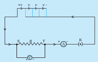
The experimental setup given in textbooks is shown below, where the voltage is varied by changing the number of cells used. A voltmeter is connected across the resistor. and an ammeter inserted in the circuit.
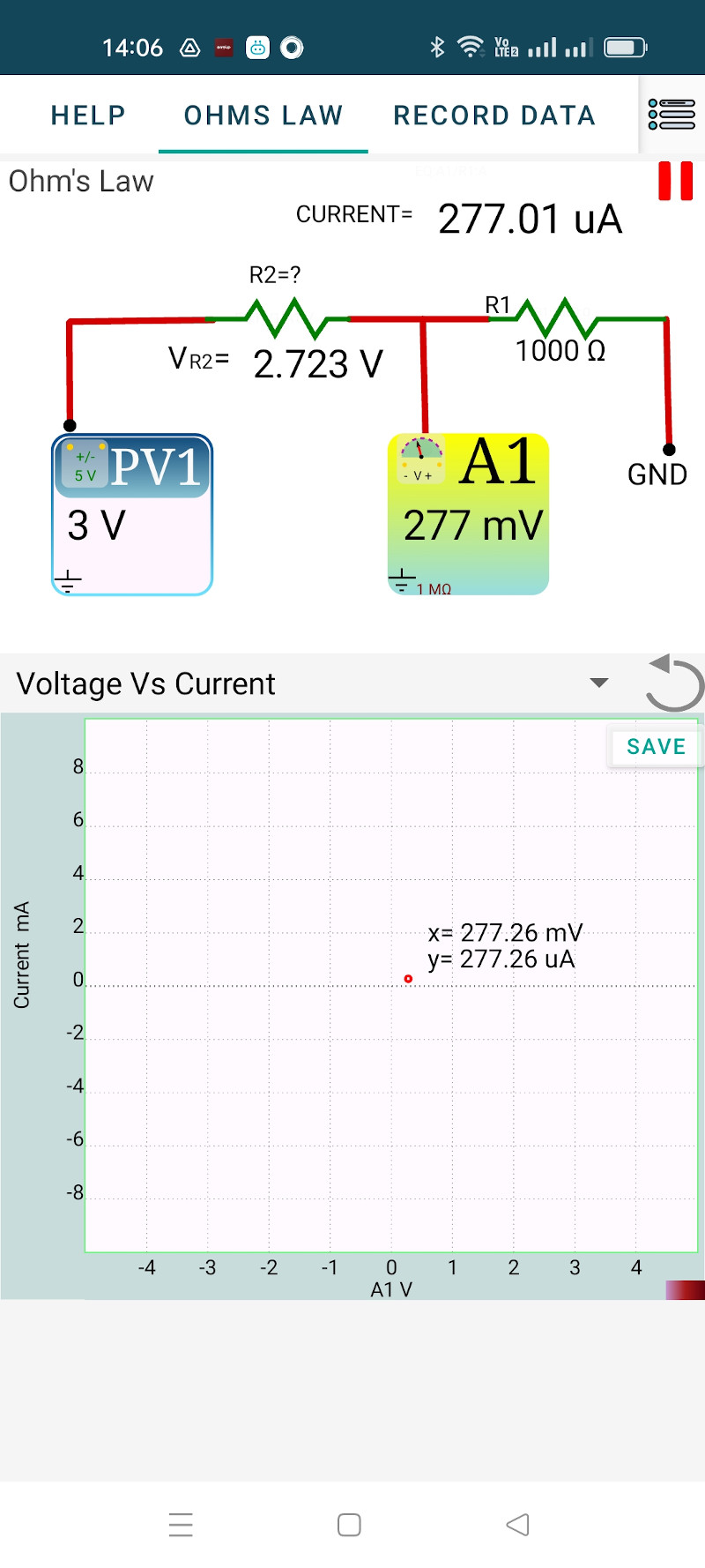
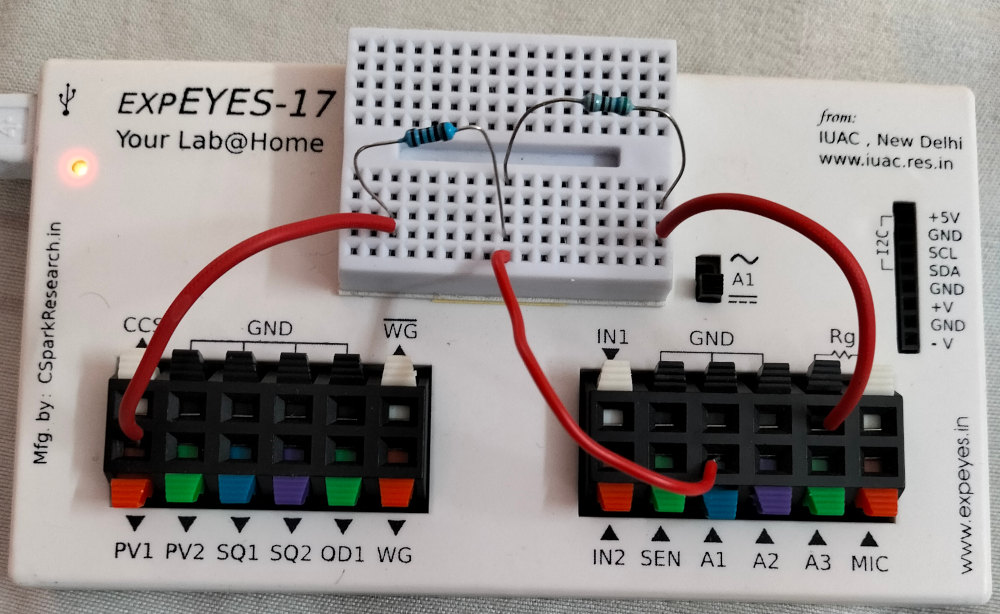
In our setup, PV1 provides the variable DC supply. The 1000 Ohm resistor along with the voltmeter A1 serves as the ammeter. Consider the 1000 Ohm resistor as a part of the measurement system. The resistor to be studied is connected between PV1 and A1.
Python program to measure resistance using Ohm’s law.
Repeat the experiment using different resistors.


Ammeters have a shunt resistor connected between the terminals and the voltage drop across the shunt is measured, amplified and displayed on a scale calibrated for current. For example, take a digital ammeter having a 0.1 Ohm shunt resistor. Assume the analog to digital converter range as 0 to 1 volt. To get 1 volt across 0.1 Ohm 10 A current is required, so the current range will be 0 to 10 A, without any amplification stage. If you want to implement a 0 to 10 mA range ammeter, the voltage across the shunt should be amplified by a factor of 1000. The shunt should be very small (zero in the ideal case) so that the insertion of meter does not affect the value f the current.
During the design f ExpEYES, integrating a current meter IC like INA219 was considered. But we decided to use the voltage drop across a 1 kOhm resistor to measure current, to reduce the complexity and cost. The method of using a 1 kOhm resistor is suitable for the experiments documented.
It is also possible to use the INA219 I2C module for current measurements.