Experiments
About
Reources
This section contains ome activities related to electricity. Performing them helps new users to become familiar with the Input/Output terminals and the software of this device. The connection diagrams for each activity is given. Different ways of drawing circuit diagrams are explained below. Read this page carefully before proceeding with the experiments.
Measuring a DC voltage : Measure the voltage between the terminals of single drycell. Also their parallel and series combinations.
Generating and Measuring Voltage : ExpEYES has programmable DC voltage sources that can be used instead of cells. This section explains how to control and measure DC voltages.
Measuring Capacitance : Measure the capacitance of different types of capacitors. Make a parallel plate capacitor using aluminium foil and measure it.
Measuring Resistance : Measure the resistance of a single resistor and their series and parallel combinations.
Light Dependent Resistors : An LDR is made of a semiconductor material that has high resistance in the dark or low light conditions and low resistance in the presence of bright light. These are explored experimentally.
Study of Ohm’s Law : Ohm’s law is explored using two resistors connected in series.
Lemon Cell : A lemon cell is constructed using Zinc and Copper Electrodes. The voltage is measured with and without connecting a load resistor to calculate the internal resistance of the cell.
DC Resistance of Human Body : A small DC voltage is applied across human body to measure it’s resistance.
Potentiometer using HB pencil : The potentiometer consists of a resistive element, usually a long, thin strip of resistive material. We are using track drawn on a paper using a lead pencil as the resistance wire.
Voltmeters on A1, A2 & A3 : There are three terminals capable of measuring DC voltages. A1 and A2 accepts voltages from -16V to +16V. A3 takes only from -3.3V to +3.3V.
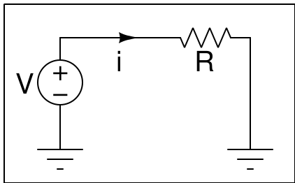
Most of the text books show circuit diagrams as shown in the diagram on the left. The same can be represented using the Ground symbol. The current loop is completed through the ground, because all points marked by the Ground symbol should connected together. They are at the same potential, generally taken as zero.
The schematics provided for all the experiments show the actual wires to be connected, the Groud symbol is not shown explicitly. For example to measure the voltage of PV1 using A1, you only need to conenct a wire between them. The complete circuit is formed as one terminal of both PV1 and A1 are internally conencted to the Ground.

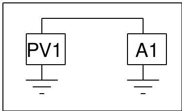
Think of PV1 as a battery having two terminals where one is conencted to the Ground. Similarly A1 as two terminal voltmeter where one terminal is connected to Ground. PV1 and A1 shares the same Ground. You may imagine a connection wire between all the points connected to the Ground symbol, they are connected together inside the device.
When you measure the voltage at PV1 of one device using another one, the ground terminals of the two must be connected together. Also when you measure the voltage of a cell, one terminal of it should be connected to the Ground and the other to A1.
Current is measured using ammeters, they have a shunt resistor conencted between the two terminals. When the current flows a voltage drop is created across the shunt resistor. This is amplified and displayed, on a calibrated scale. For example, take a digital ammeter having a 0.1 Ohm shunt resistor. Assume the analog to digital converter range as 0 to 1 volt. To get 1 volt across 0.1 Ohm 10 A current is required, so the current range will be 0 to 10 A, without any amplification stage. If you want to implement a 0 to 10 mA range ammeter, the voltage across the shunt should be amplified by a factor of 1000. The shunt should be very small (zero in the ideal case) so that the insertion of meter does not affect the circuit current.

During the design of ExpEYES, integrating a Current Sensing Amplifier IC was considered. But finally we decided to use the voltage drop across a larger resistor (1 $ k\Omega $) for current measurements, minimizing the complexity and cost. The method of using a 1 kOhm resistor is suitable for all the experiments documented. It also measures current across negative voltages, something lacking in most of the CSA ICs.
The external I2C module INA219 is also supported for current measurements.
You can measure capcitance values ranging from several picoFarads to 100 microFarad. The capaciance is measured by injecting a fixed amount of charge and measuring the resulting voltage, $ C=\frac{Q}{V} $. One should not touch the plates or terminals during the measurement, doing so results in error.