Experiments
About
Reources
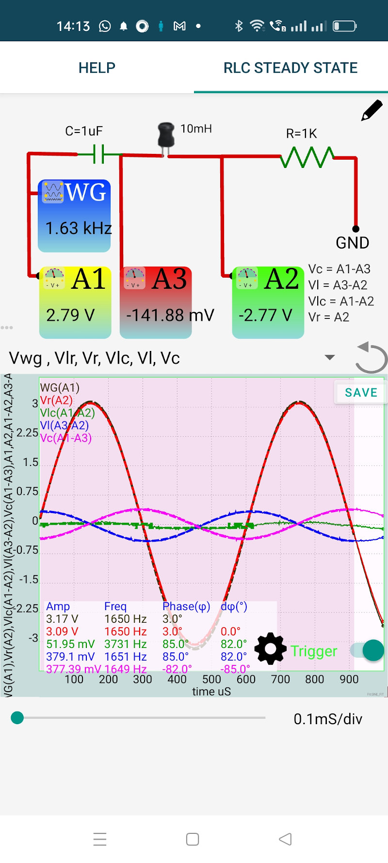
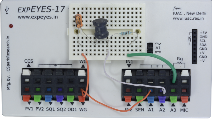
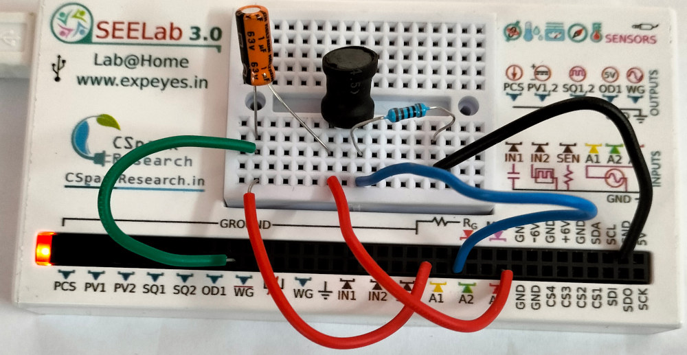
The objective is to study the behavior of a RLC series circuit under an applied sinusoidal voltage. The resulting voltage amplitudes across the elements and their phase relationships are measured. The series resonance is studied by measuring the total voltage across LC and the voltages across L and C separately at resonance. The connections are shown in the screenshot below. photograph of the setup for both ExpEYES-17 and SEELab3 hardware are shown.
We have chosen a 1uF capacitor, 10mH inductor and 1000 Ohm resistor. The applied frequency is chosen as 1600 Hz to start with. This is adjusted to get zero phase difference across LC (between A1 and A2). It can be seen that at resonance the entire voltage is dropped across the resistor and there is no voltage drop across L and C together. But the voltage across each element is not zero, they become equal in magnitude and 180 degree out of phase.
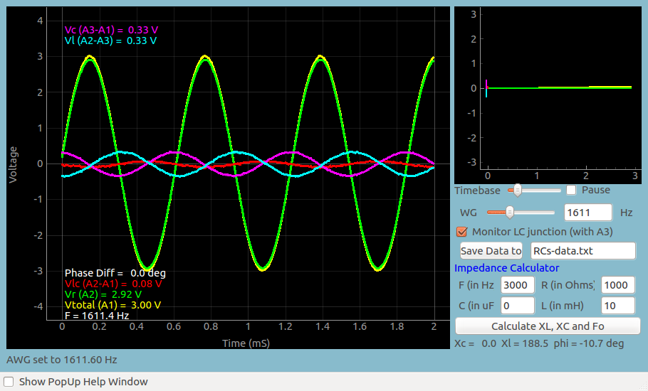
Result of the same experiment done on the PC is shown below.