Experiments
About
Reources
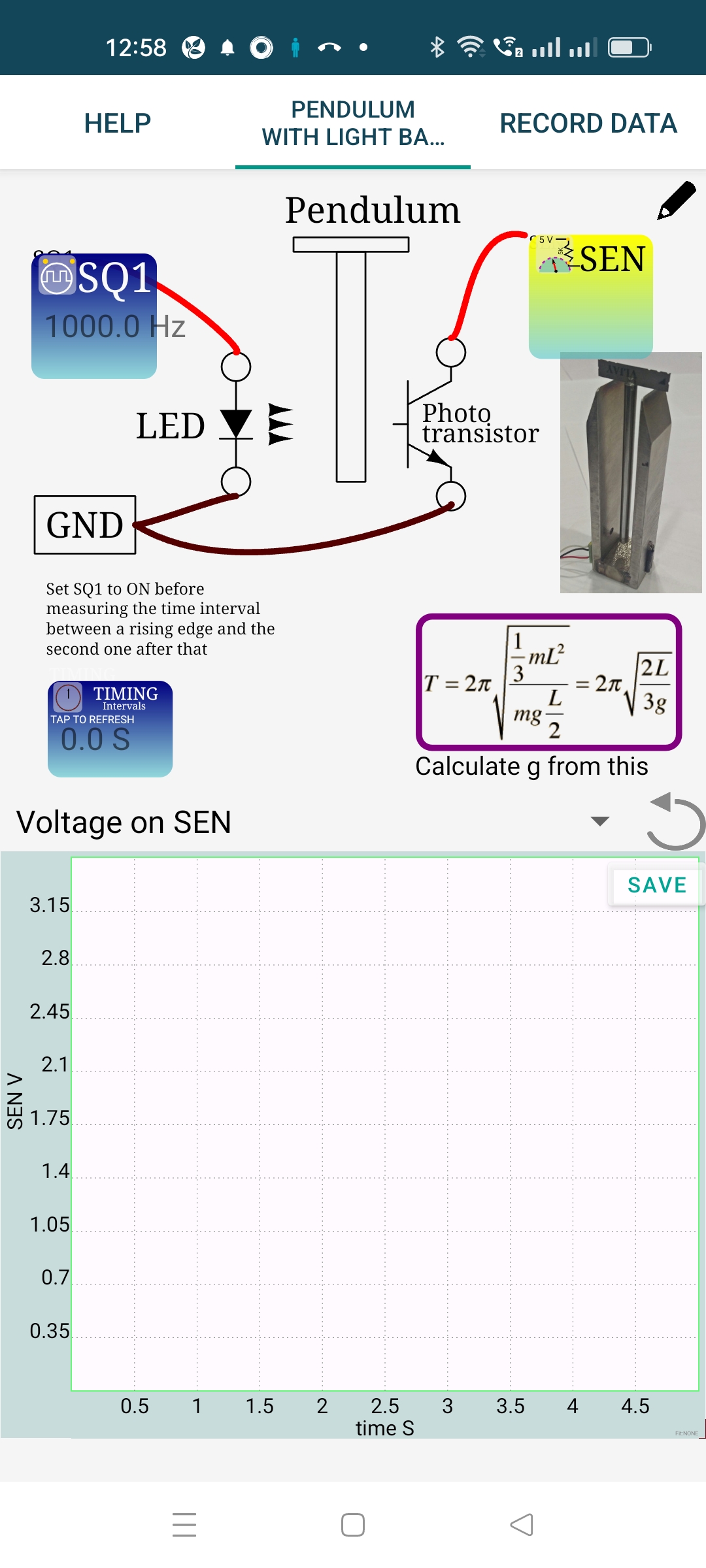
A pendulum is made to intercept a light beam and the time interval is measured. The light source is a White LED connected to SQ1. LED can be directly connected between SQ1 and Ground, because SQ1 has an internal 100 Ohm series resistor. The phototransistor collecor is connected to SEN and emitter to the Ground. The connections can be tested by setting SQ1 to generate a pulse and observing the same on SEN. From the GUI you can control the LED.
The pendulum is made to oscillate between an LED and a photo-transistor. The light falling on the photo-transistor is inercepted during the oscillations. A rod pendulum is chosen only because it is easier to handle.
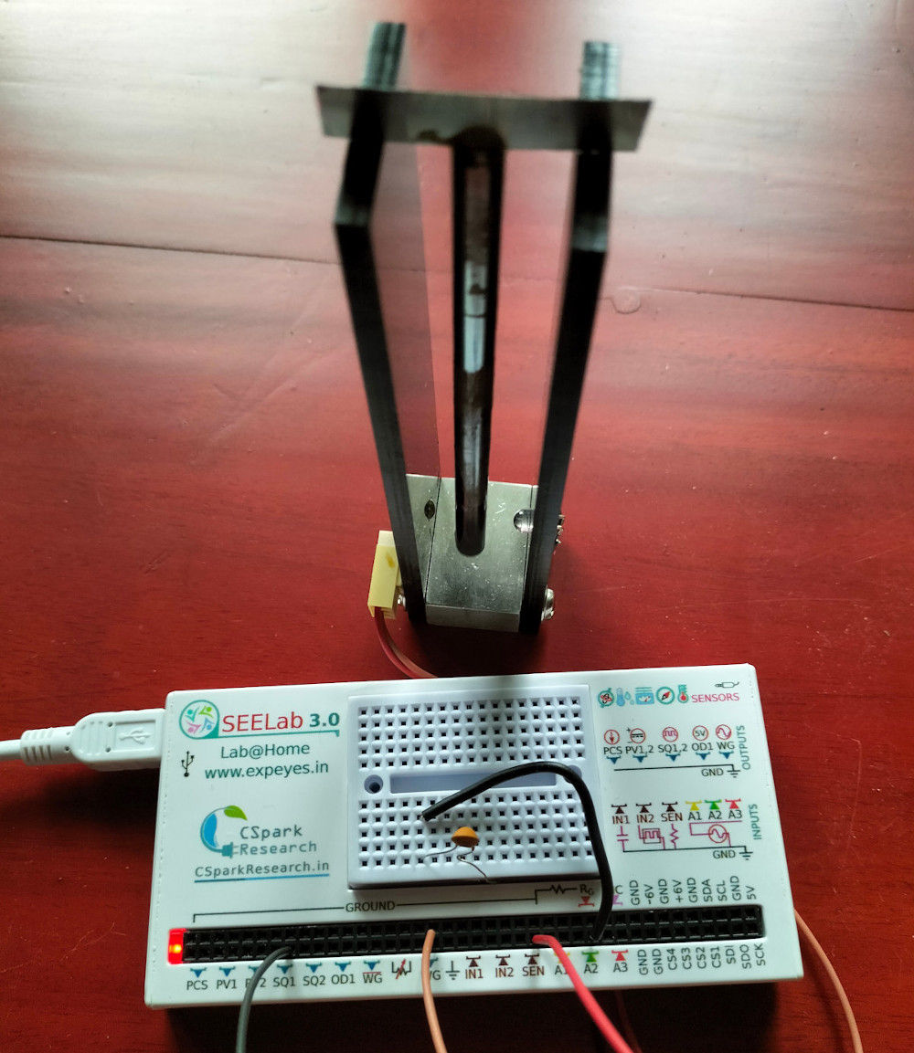
A photograph of the experimental setup is shown below. The time period is measured with an error less than 100 microseconds. It is possible to observe the effect of amplitude on the period.
In our experimental setup, the phototransistor is connected from SEN to ground. SEN is internally connected to 3.3 volts via a 5.1k resistor. When light falls on the transistor SEN will be low. Intercepting light will generate a rising edge on SEN.
The function call multi_r2rtime(‘SEN’, 2) returns the time interval for 2 cycles, returning of the pendulum is to be skipped.
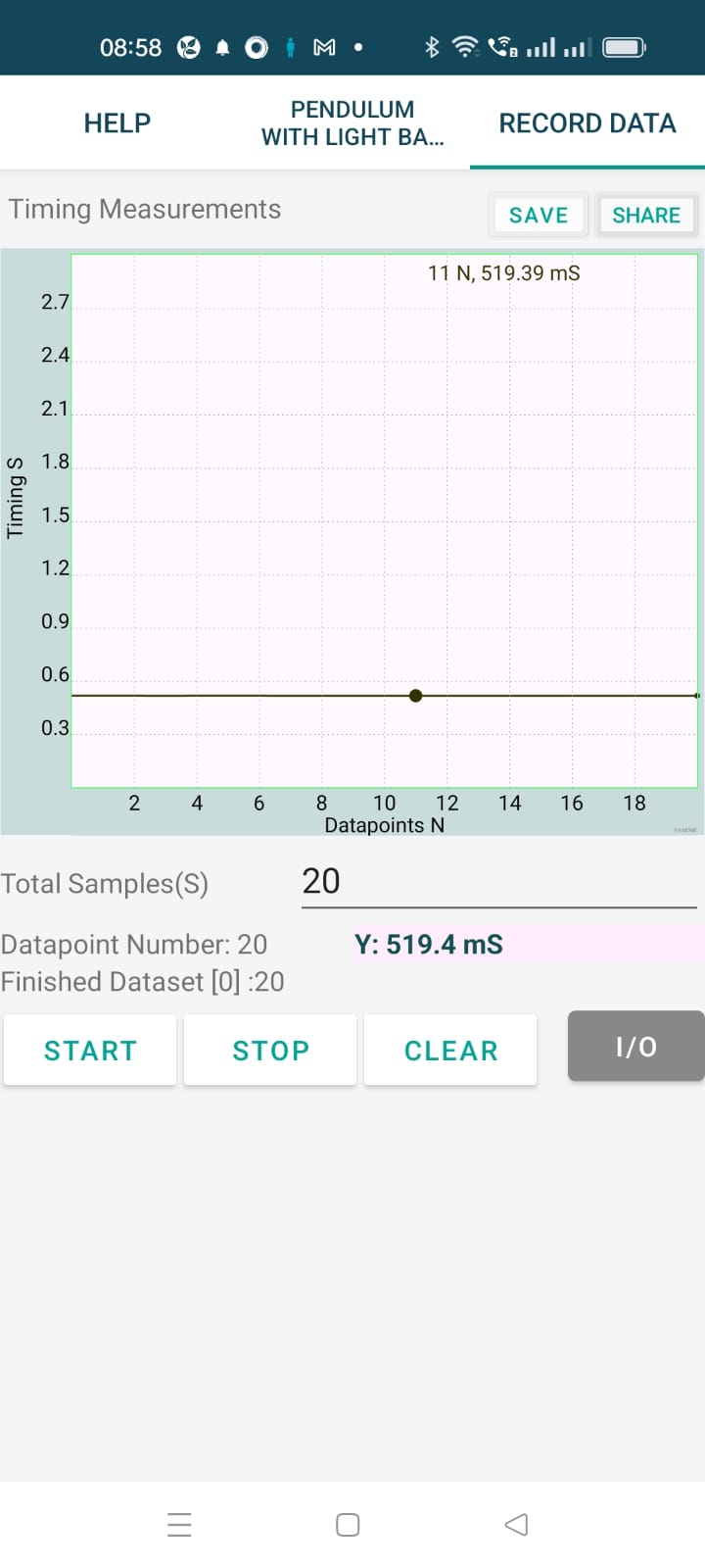
The result of the program is shown below. There are two main sources of error:
The result is very close o the actual value, may be due to some errors cancelling each other. What is important is the very low spread in the time measurement (around 0.1 mS). It is good enough to study the large amplitude effects.
You can make compound pendulums having various shapes and make measurements. The torsion pendulum time period also can be measured using a photo-transistor and LED combination.